Male Blind Sub 2 FIG 1502 1/2 NPT with Wing Nut (15,000 PSI)
High-Pressure Flowline Blanking with Integrated Pressure Monitoring
In high-pressure well servicing, hydraulic fracturing, flowback manifold routing, and cementing operations, isolating fluid piping branches safely is a mandatory operational requirement. A heavy-duty Male Blind Sub 2 FIG 1502 1/2 NPT unit provides a reliable mechanical end-cap designed to seal female hammer union sub ends while offering fluid access for pressure monitoring or bleed-off routines.
Engineered from heat-treated AISI 4130 forged alloy steel and rated for 15,000 PSI Cold Working Pressure (CWP), each Male Blind Sub 2 FIG 1502 1/2 NPT assembly incorporates an integrated 1/2″ Female NPT auxiliary port. This design enables operators to install pressure gauges, transducers, or relief valves directly into the terminal point of temporary surface piping spreads without altering manifold blocks. For broader configurations, explore our plug union male female test plug blanking blind line.
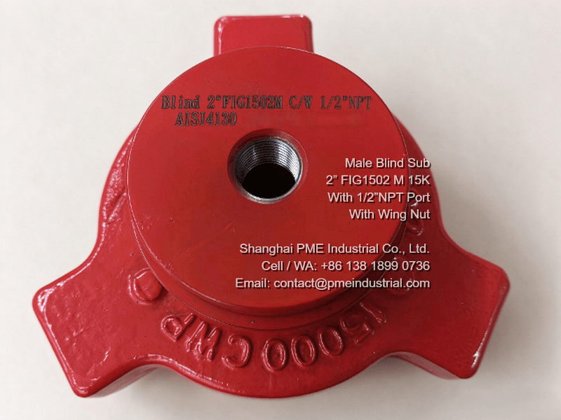
Traceable alloy steel forging rated at 15,000 PSI CWP with laser-etched serial numbers.
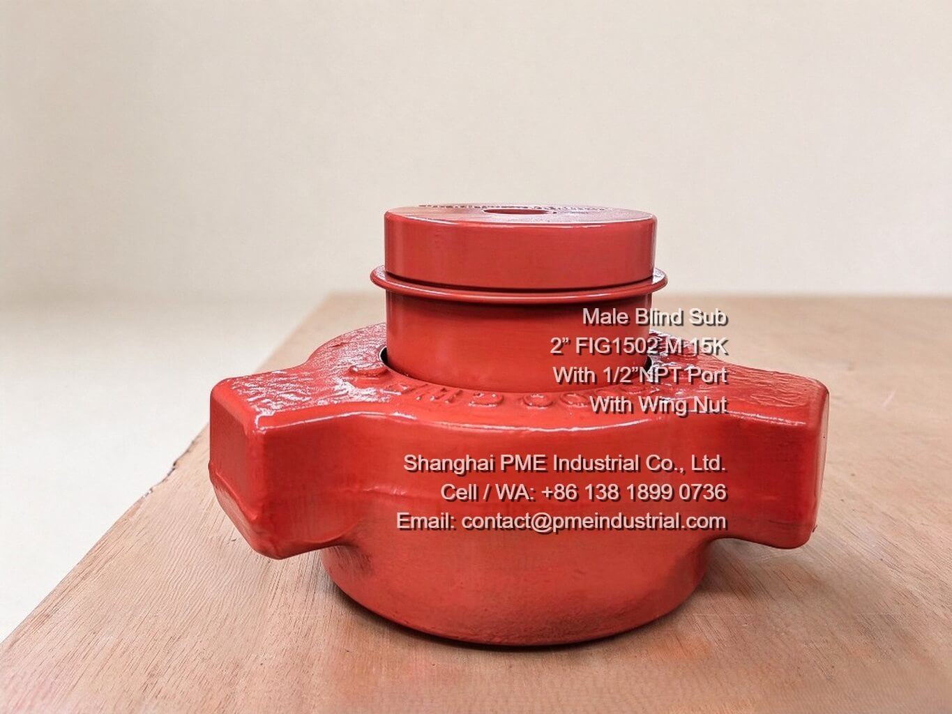
Rugged ACME thread design allowing rapid field makeup with standard sledgehammers.
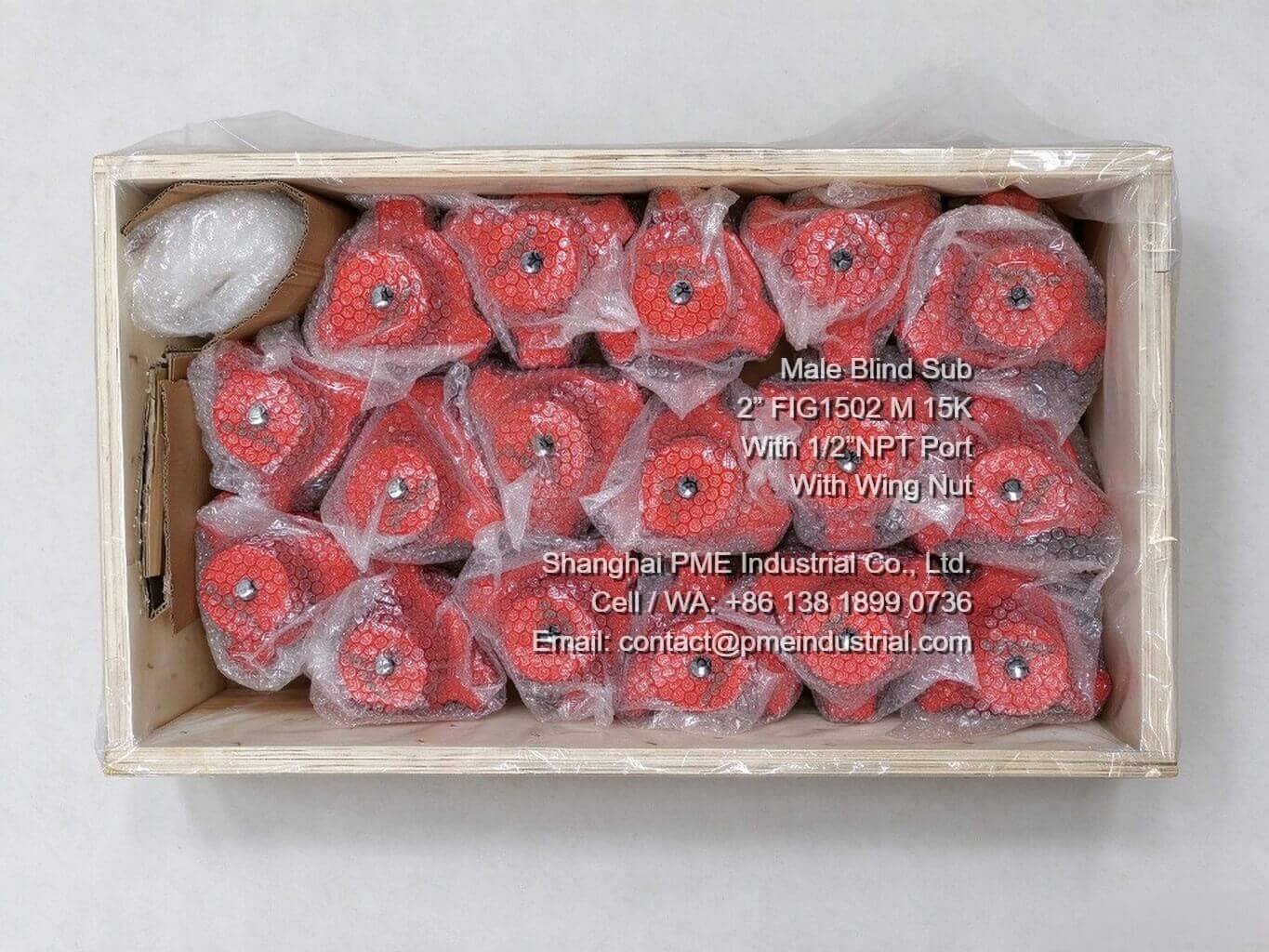
Rust-inhibited coating and crate packaging ready for global oilfield dispatch.
Technical Comparison: Male Blind Sub 2 FIG 1502 1/2 NPT vs. Solid Blind Sub
When selecting isolation subs for high-pressure flowlines, field engineers must evaluate whether a solid dead-end cap or a tapped Male Blind Sub 2 FIG 1502 1/2 NPT best suits operational requirements. Understanding these technical differences prevents line modification on site:
1. Connection Style & Auxiliary Functionality
With 1/2″ NPT Port: Features a center-drilled, precision-tapped 1/2″ Female NPT thread through the body center. This allows direct installation of pressure sensors, needle valves, or sampling ports directly at line termination points.
Without 1/2″ NPT Port (Solid): Manufactured as a fully solid, continuous alloy steel forging without internal penetrations. It acts strictly as a mechanical fluid barrier.
2. Installation Speed & Pressure Bleed-Off Safety
With 1/2″ NPT Port: Enhances site safety during line breakdown. Before hammer union wing nuts are loosened, operators can open an attached NPT bleed valve to verify zero residual line pressure, preventing hazardous trapped fluid release.
Without 1/2″ NPT Port (Solid): Requires upstream line venting before break-out. If pressure remains trapped behind a solid blind sub, hammer break-out carries higher operational risk.
3. Application Scenarios & Sealing Performance
With 1/2″ NPT Port: Ideal for well testing spreads, frac manifold end-caps, pump discharge monitoring, and pressure testing setups where continuous data logging is necessary.
Without 1/2″ NPT Port (Solid): Recommended for permanent or semi-permanent blind dead-ends where no auxiliary fluid access or instrumentation is permitted.
AISI 4130 Forged Material Metallurgy & Manufacturing Standards
PME components are forged from high-tensile AISI 4130 alloy steel, undergoing quenched and tempered heat treatment to achieve optimal mechanical properties. Key engineering characteristics include:
- Working Pressure Rating: 15,000 PSI Cold Working Pressure.
- ACME Threads: Machined with robust ACME hammer union threads for rapid makeup and breakout using standard sledgehammers or pneumatic tools.
- Traceability & Testing: Each sub is individual serial-numbered and supplied with Material Test Reports (MTRs), magnetic particle inspection (MPI), and hydrostatic pressure test certificates.
Technical Specifications Comparison Table
| Parameter | Male Blind Sub with 1/2″ NPT | Solid Male Blind Sub (Without NPT) |
|---|---|---|
| Nominal Size & Fig | 2″ FIG 1502 | 2″ FIG 1502 |
| Working Pressure (CWP) | 15,000 PSI | 15,000 PSI |
| Body Material | Forged Alloy Steel AISI 4130 | Forged Alloy Steel AISI 4130 |
| Auxiliary Port Thread | 1/2″ Female NPT (NPT Plug included) | None (Solid Body) |
| Service Medium | Standard Service / Sour Gas (H2S NACE MR0175) | Standard Service / Sour Gas (H2S NACE MR0175) |
Typical Oilfield Application Scenarios & Selection Guidance
Choosing between these two sub configurations depends on the position within the surface fluid routing spread:
- Frac Manifold Outlets: Use 1/2″ NPT tapped blind subs at unused outlet valves to allow direct mounting of electronic pressure transducers during hydraulic fracturing stage monitoring.
- Flowback Line Terminals: Install NPT-tapped blind subs with needle valves at line ends to bleed off residual pressure safely before breakdown.
- Coiled Tubing & Cementing Iron: Use solid blind subs for terminal line plugs where no auxiliary tapping or sensor port is required by field safety standards.