
How to Select the Right FIG 1502 Crossover for Oilfield Flowline Applications
The Critical Role of Crossover Adapters in High-Pressure Oilfield Flowlines
In high-pressure well servicing, hydraulic fracturing, flowback, and cementing operations, temporary surface piping spreads require seamless transitions between varying pipe diameters, end connection profiles, and pressure boundaries. A high-performance FIG 1502 crossover adapter serves as the critical mechanical bridge connecting disparate flowline assets. Choosing the proper crossover fitting ensures fluid continuity while preserving pressure containment across demanding wellsite setups.
However, misidentifying connection end types or assuming universal cross-compatibility between different connection styles can compromise site safety and lead to costly non-productive time (NPT). Selecting the correct crossover requires a thorough evaluation of line size transitions, end-connection geometry, temperature ratings, medium aggressiveness, and pressure limits.
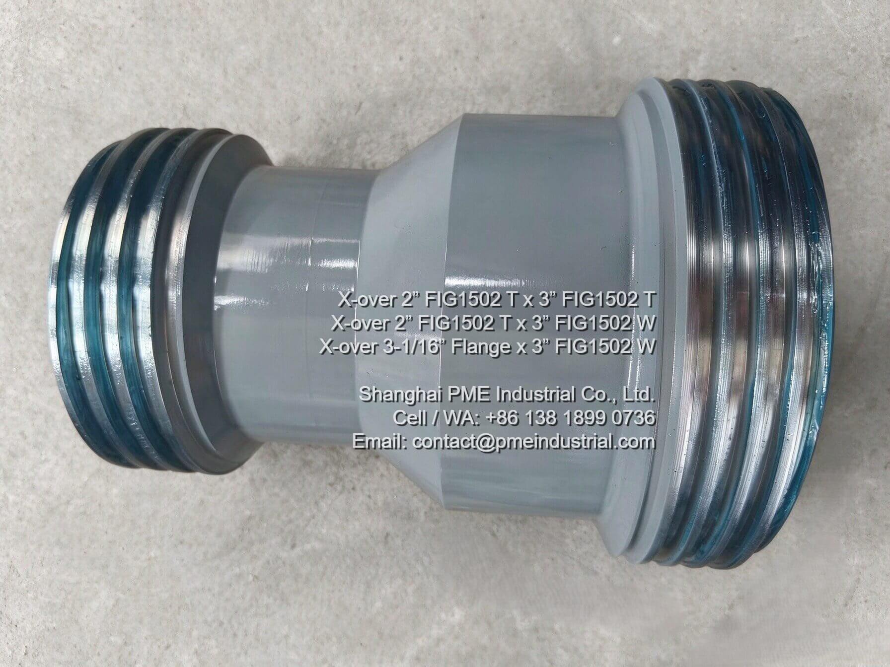
Dual threaded end configuration for size transition in line piping.
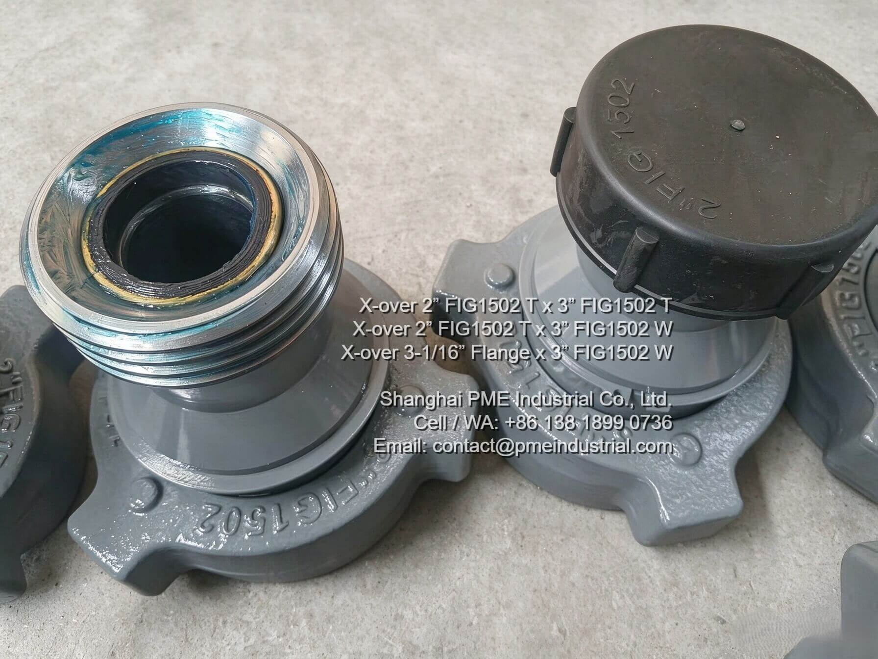
Transition adapter linking threaded pipe ends to Wing hammer union connections.
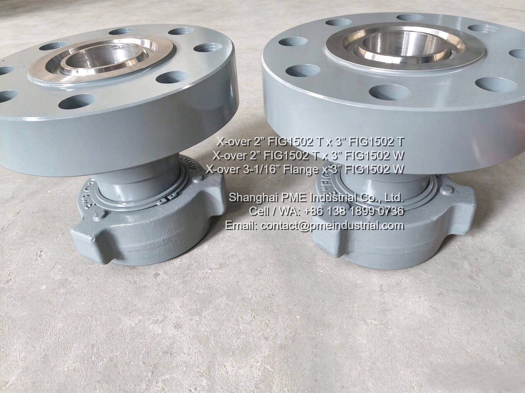
Flange-to-Wing adapter designed for direct mounting to manifold stacks.
Understanding End-Connection Geometries: FIG 1502 Threaded (T), Wing (W), and Flanged Styles
A common source of confusion in fluid line specification is the distinction between Threaded (T) and Wing/Hammer Union (W) style end profiles. In industrial flowline terminology, these designations represent fundamental mechanical differences and must never be assumed interchangeable without verifying exact connection geometry:
- Threaded Connections (T): Feature precision-machined line pipe threads (e.g., NPT or API threads) designed to thread directly into matching female pipe ports or sub-assemblies.
- Wing / Hammer Union Connections (W): Feature standard hammer union profiles (male sub, female sub, and wing nut) that utilize an elastomeric lip seal for fast makeup and breakout using sledgehammers or hydraulic tools.
- Flanged Connections: Incorporate ring joint flange faces (such as API 6A flange profiles with ring gaskets) to provide rigid, high-bolting-torque connections directly to wellhead equipment, blowout preventers (BOPs), or choke manifolds.
When choosing high pressure crossover fittings, buyers must verify the precise sex (male vs. female), thread type, and seal design of both ends to ensure complete compatibility.
Detailed Technical Evaluation of Featured FIG 1502 Crossover Configurations
1. X-over 2” FIG1502 T x 3” FIG1502 T
Configuration & Connection Style: Features a 2-inch FIG1502 Threaded (T) connection on one end and a 3-inch FIG1502 Threaded (T) connection on the opposite end.
Engineering Application: Designed specifically for line size transitions within threaded high-pressure piping assemblies. It allows operators to step down or step up nominal line diameters between 2-inch and 3-inch flow channels while maintaining threaded engagement.
Key Procurement Note: Verify exact thread specification (e.g., NPT or line pipe thread size and length) with the manufacturer prior to ordering to ensure thread engagement depth and pressure rating match system design requirements.
2. X-over 2” FIG1502 T x 3” FIG1502 Wing
Configuration & Connection Style: Combines a 2-inch FIG1502 Threaded (T) end with a 3-inch FIG1502 Wing Hammer Union (W) end.
Engineering Application: Serves as a hybrid connection adapter between threaded manifold outlets/pipe lines and standard 3-inch hammer union flow lines. It enables rapid rigging of temporary flowback or treating lines to fixed threaded equipment.
Key Procurement Note: Ensure whether the 3″ FIG1502 Wing side is configured as a Male Sub, Female Sub, or complete Wing Nut assembly, as union gender dictates field installation compatibility.
3. X-over 3-1/16” Flange x 3” FIG1502 Wing
Configuration & Connection Style: Integrates a 3-1/16” API flanged connection on one end and a 3-inch FIG1502 Wing (W) hammer union connection on the other.
Engineering Application: Engineered for direct interface with flanged wellhead valves, BOP outlets, or high-pressure choke manifold blocks, converting rigid flanged connections into quick-connect hammer union flowlines.
Key Procurement Note: Confirm flange API pressure rating (e.g., 5,000 PSI, 10,000 PSI, or 15,000 PSI), ring groove type (e.g., BX or R series), and bolting pattern with engineering personnel before finalizing orders.
Crossover Selection Comparison Matrix
The comparison table below outlines key technical considerations for evaluating crossover fittings during procurement planning:
| Crossover Model | End Connection 1 | End Connection 2 | Primary Application | Technical Data to Confirm Prior to Purchase |
|---|---|---|---|---|
| 2″ FIG1502 T x 3″ FIG1502 T | 2″ FIG1502 Threaded (T) | 3″ FIG1502 Threaded (T) | Threaded line diameter transition | Thread specification (NPT/API), overall length, bore ID, material grade. |
| 2″ FIG1502 T x 3″ FIG1502 Wing | 2″ FIG1502 Threaded (T) | 3″ FIG1502 Wing (W) | Threaded to hammer union transition | Union gender (Male/Female/Nut), seal material, working pressure rating. |
| 3-1/16″ Flange x 3″ FIG1502 Wing | 3-1/16″ API Flange | 3″ FIG1502 Wing (W) | Flange to Wing quick-connect adapter | Flange pressure rating, ring groove type, bolt hole circle, union sub gender. |