
4 inch FIG 207 Blanking Union 2000 PSI CWP ASTM A105
Engineering Overview: Terminal Line Blanking in Medium-Pressure Flow Systems
In industrial fluid handling, offshore logistics, and petroleum processing plants, isolating fluid lines or terminating manifold branches is a standard operational requirement. Piping engineers evaluate appropriate hammer union configurations when isolating terminal lines. Using a standard flow-through union paired with a separate blind flange or threaded cap introduces additional connection points and assembly steps during field makeup and breakout.
To streamline line isolation, purpose-built blanking unions integrate an internal blanking plug directly into the sub structure. Specifically, the 4 inch FIG 207 Blanking Union provides line closure rated for 2,000 PSI Cold Working Pressure (CWP). Constructed with a Schedule XS butt weld end connection and forged from ASTM A105 carbon steel, this union provides fluid containment while maintaining standard hammer union wing nut operation.
For offshore yards, bunkering terminals, and fluid equipment integrators operating in Southeast Asia, sourcing traceable FIG 207 Singapore stock meeting pressure vessel material standards supports offshore maintenance and pipeline projects.
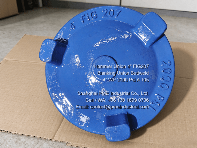
External view of 4 inch FIG 207 blanking cap displaying forged 2000 PSI markings and three hammer lugs.
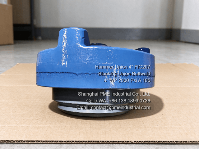
Side view showing blue blanking cap assembled over the grey male sub, with protective grease applied to the joint edge.
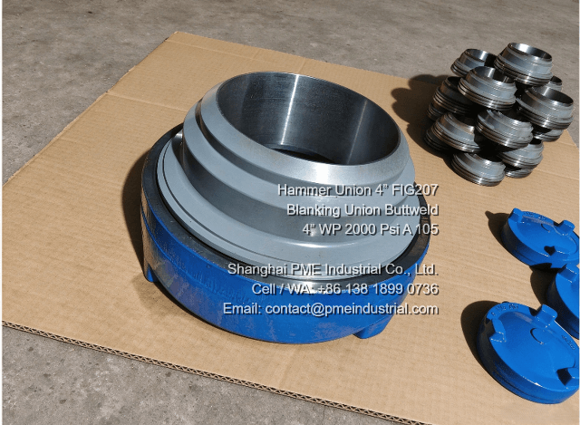
Grey male sub showing the machined butt weld bevel and internal step dimensions for Schedule XS piping.
Technical Comparison: FIG 207 vs FIG 206 / FIG 602 / FIG 1002 / FIG 1502
Selecting fluid line fittings requires evaluating structural and functional differences across hammer union figures. While flow-through unions like FIG 206 or high-pressure lines like FIG 1502 serve continuous flow paths, the FIG 207 series addresses terminal line closure. Reviewing Hammer Union Pressure Ratings assists in selecting fittings suited to system parameters.
1. Structural Purpose: Dedicated Blanking vs. Flow-Through
The distinction in FIG 207 vs FIG 206 design involves fluid passage. FIG 206, FIG 602, FIG 1002, and FIG 1502 unions feature dual open ends (male sub and female sub) for continuous flow. The FIG 207 operates as a blanking union, replacing the standard female flow sub with a solid cap structure to close the line terminal without extra blind flanges or threaded caps.
2. Pressure Classifications
Hammer unions are specified by working pressure rating. A 2000 Psi Blanking Union like the FIG 207 provides reliable line termination at specified working pressures. FIG 206 shares a 2,000 PSI CWP rating, enabling dimensional interchangeability between FIG 206 and FIG 207 mating parts. Higher pressure figures such as FIG 602 (6,000 PSI), FIG 1002 (10,000 PSI), and FIG 1502 (15,000 PSI) serve high-pressure services like hydraulic fracturing and choke manifolds.
3. Component Interchangeability Advantages
Because the FIG 207 utilizes standard ACME thread profiles and male sub dimensions matching the FIG 200 and FIG 206 series, operators can convert an existing FIG 206 line end to a blanked terminal by replacing the female sub with a FIG 207 cap. This interchangeability supports spare parts management in rig and vessel inventory.
Hammer Union Figure Comparison Matrix
| Union Figure | CWP Rating | Primary Function | FIG 207 Interchangeability |
|---|---|---|---|
| FIG 207 | 2,000 PSI | Line Blanking / Isolation | Base Standard |
| FIG 206 | 2,000 PSI | Flow-Through Line Connection | Compatible Threads/Subs |
| FIG 602 | 6,000 PSI | High-Pressure Manifolds | Not Interchangeable |
| FIG 1002 | 10,000 PSI | High-Pressure Well Servicing | Not Interchangeable |
| FIG 1502 | 15,000 PSI | Frac Iron & Treating Lines | Not Interchangeable |
Product Specification: 4″ FIG 207 ASTM A105 Buttweld Union (Sch. XS)
PME manufactures the 4 inch FIG 207 Blanking Union according to material and dimensional standards for industrial and marine applications. Forged from ASTM A105 carbon steel, this component provides structural strength for cold working pressures up to 2,000 PSI.
Key Technical Parameters:
- Nominal Size: 4 Inch (DN100)
- Union Figure: FIG 207 Blanking Type
- Pressure Rating: 2,000 PSI Cold Working Pressure (CWP) / 3,000 PSI Hydrostatic Test Pressure
- End Connection: Butt Weld End, Schedule XS wall thickness bevel
- Body Material: Forged Carbon Steel ASTM A105 Buttweld Union construction
- Service Medium: Standard Service (Water, Oil, Gas, Fuel Transfer)
Selecting an ASTM A105 Buttweld Union with Schedule XS end preparation supports direct welding onto 4-inch carbon steel piping systems. The butt weld joint provides a permanent connection suitable for systems subject to vibration and thermal variation in marine fuel piping and plant lines.
Industrial Applications & Regional Suitability
The 4-inch FIG 207 union is used in medium-pressure liquid and gas handling systems requiring line access or terminal blanking. Primary applications include:
- Marine & Bunkering Terminals: Blanking manifold discharge lines on tankers, supply vessels, and bunkering barges.
- Water & Slurry Transfer: Closing utility water, drilling mud suction lines, and low-pressure cement manifold branches.
- Industrial Plant Piping: Providing inspection access points on fuel transfer lines.
- Offshore Maintenance: Serving as reusable pressure caps during equipment flushing and hydro-testing routines.
In maritime hubs like Singapore, shipyard contractors and offshore service providers select certified hammer union inventory. Shanghai PME Industrial supplies 4″ FIG 207 units with Mill Test Reports (MTRs) complying with EN 10204 3.1 for industrial and marine projects in Singapore and Southeast Asia.